The DIY turbo build thread

CMF_Danvillan

» CMF Member
Member since:
Posts:
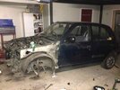
So I'm currently in the process of building a 1995 Micra SLX
Unlike some of the cashed up builds you have seen in the past on this forum, I'm trying to build a turbo'd Micra on somewhat of a budget with a lot of the parts supplied by member on this forum.

When I decided to build this car I did so with the intention to learn as much as possibly in relation to a lot of different things I have never done before eg striping and rebuild a motor, working with fibreglass, welding, and spray painting. So the best way to learn is to DO IT YOURSELF.

I don't have any type of mechanical trade background and limited mechanical knowledge. What I do is research, research some more and ask questions.

For me I get a sense of achievement to do things for myself even if it doesn't turn out that well, I guess thats how you learn.

So I have decided to create a build thread which outlines the journey of the DIY turbo build.

The projects I have planned to do myself are as follows:

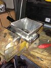
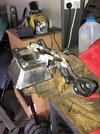
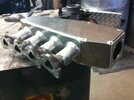
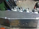
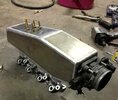
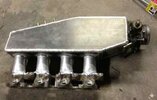
DIY side feed intake plenum
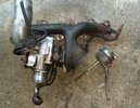
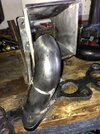
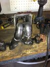
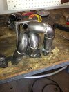
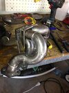
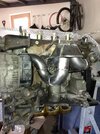
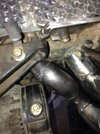
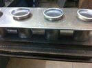
DIY Turbo manifold and dump pipe
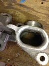
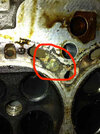
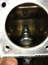
DIY Head port and polish
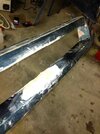
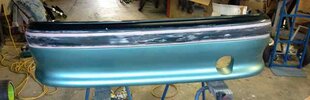
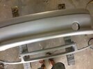
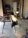
DIY Full respray
DIY mandrel bent exhaust system
Alot more as I go along, I will try and update this thread regularly.

I have created a couple of DIY threads already and thought I might as well put it all into one thread.

Previous DIY threads:

DIY cold air intake box = https://micra.org.uk/cmf/message/82137

DIY Pillar gauge pods =
https://micra.org.uk/cmf/message/81873

The plan is to do as much as I can on my own and save as much money as I can on the way.

Wish me luck.... ;p
 

CMF_Danvillan

» CMF Member
Member since:
Posts:
CG13de standard bottom end
Ported and polished Head decompressed to 8.2:1 (hopefully with some Poncam)
4.3 kg JUN flywheel
Datrat clutch
DIY Side feed intake plenum with sr20 TB
T25 Garrett turbo
DIY turbo manifold and Dump pipe
Sr20 injectors with custom fuel rail
EMS 4424 Stinger
XR6 Front mount intercooler 200x 700
walbo fuel pump
adjustable fuel regulator
HKS front coilovers
camber bolts
Whiteline anti lift castor kit
Whiteline lower control arm brace
Nismo gauge cluster

Some of the parts ready for the build plenty more to come no doubt.

So this is the Micra in her current state.......
 

Attachments

  • 82215.jpg
    82215.jpg
    28.4 KB · Views: 60

CMF_RTK

» CMF Member
Member since:
Posts:
you wont drop compression with just port and polish, you will need a thick head gasket or run 2 standards, or go one better and run decompressed pistons, you can still get good boost/power without decomping the engine JCMicra on here, runs standard engine with Haltec Platinum 500 ECU, with 10 psi and getting 170ish HP at the wheels (having fuel spark problems from what he has told me, going coilpacks)
 

CMF_Danvillan

» CMF Member
Member since:
Posts:
DIY SIDE FEED INTAKE PLENUM

So the other day I went to the local sheet metal fabricator and bought some aluminium sheet for the job.

Got a piece of 4mm marine grade aluminium and 6mm aluminium, also some 32mm aluminium pipe. Cost me $20 pretty cheat for a custom plenum

Started by cutting the intake flange off the OEM manifold.

I then sat down did a bit of research on plenum designs and drew up my design.
Majority of the plenums you see are round made from 4 inch pipe but I'm making mine boxed (just easier for me and it is not the major factors to worry about when designing the plenum).

The factors that need to be considered are:-
1. Plenum volume (some say it should be twice the volume of the engine capacity)
2. The ratio between the plenum diameter and each cylinder
3. Air flow and friction within the plenum.

So my design is a little less than 3 litres in volume roughly twice the engine capacity should be able to deal with the turbos compression.

The ratio between the cylinder I aimed for were cylinder 4 =100%, cylinder 3 = 86% cylinder 2= 70%, cylinder 1 = 50%. If cylinder 1 is 50% of cylinder 4 generally the line between cylinder 2 and 3 should follow that %.

In relation to air friction within the plenum, the runners will be feed about 10 to 15mm off the floor of the plenum. The runner will also have bellmouth endings to assist the flow of air.

Once the design was drawn up it was transferred to the aluminium sheet.
No hi tech laser cutters here just a jigsaw, hole saw and file were used to cut the pieces.

To be noted - I used the 6mm Aluminium for the TB flange which the SR20 TB will be drill and tapped. I also used the 6mm for the longer top piece so I can tap the vacuum line into it.
 

Attachments

  • 82218.jpg
    82218.jpg
    24.8 KB · Views: 49

CMF_Danvillan

» CMF Member
Member since:
Posts:
RTK as frank said Quench step will be removed to drop the compression.

Hey Frank what do I need to watch out for when removing the quench step, don't go past the point of the head gasket or is there something else I should be watching out for?

Thanks
 

CMF_Danvillan

» CMF Member
Member since:
Posts:
Solution... press the end in a vice till it takes the oval shape of the OEM intake. As seen on the photo above the top is round and the bottom matches closely to OEM intake manifold.
 

Attachments

  • 82222.jpg
    82222.jpg
    30.8 KB · Views: 40

CMF_Danvillan

» CMF Member
Member since:
Posts:
Once pressed the pipe is a little bigger than the standard intake so I rounder the edge off to smooth out the air flow a bit.

Anyway I'm not going to attempt to weld this this myself when I have a friend who can TIG weld aluminium and will do it for free (suppose it will cost me a case of beer).

The only this I haven't figure out yet is how I'm going to get the end of the runner bellmouthed? Hopefully my friend will have a solution.
 

Attachments

  • 82223.jpg
    82223.jpg
    29.6 KB · Views: 44

CMF_frank2

» CMF Member
Member since:
Posts:
Danvillan WROTE:

"RTK as frank said Quench step will be removed to drop the compression.

Hey Frank what do I need to watch out for when removing the quench step, don't go past the point of the head gasket or is there something else I should be watching out for?

Thanks

i think they,re important in terms of DET resistance dan, i would cut them scallop shaped personally (leaving the actual step intact) and then cut the bowls to the full H/G dia and into the corners.
you could also have the seats cut 1mm or so to drop the c/r more eh, and then tickle the stem ends down for exact valve clearance
 

CMF_Danvillan

» CMF Member
Member since:
Posts:
Frank, I noticed in the past you have remove the quench steps on one of your engines. Did you have dramas when you did it? How exactly does the quench step resist DET? Only reason I ask is because in the past you have recommended this as a way to lower c/r, just wondering what has changed your mind about this method.
 

CMF_asdame

» CMF Member
Member since:
Posts:
hey m8

I started out bout the same way. I was a product designer but luv tinkering with mechanical/electrical stuff.
Since I brought my first micra, just built my knowledge & experience of working on the car simply by researching, designing, building and testing.

if I didn't have the required skill/resource, either outsource it if times limited, or learn the new skill myself by reading and doing if there's free time and can afford the equipment.

best ppl I know who make DIY performance mods on a budget n suggest checking out are either frank or ebbdude

I've also got a detailed diary blog of my micra turbo's modding history start to finish that may help you.
here's a seperate linked Index page to my blog to find things bit easier cos its least 70 pages long :p

http://www.micra.org.uk/threads/pollymobiles-rebuild-blog-index.52496/
 

CMF_frank2

» CMF Member
Member since:
Posts:
Danvillan WROTE:

"Frank, I noticed in the past you have remove the quench steps on one of your engines. Did you have dramas when you did it? How exactly does the quench step resist DET? Only reason I ask is because in the past you have recommended this as a way to lower c/r, just wondering what has changed your mind about this method.

i only tested it out on 1 chamber dan, and never ran it, and i think they are important for the combustion/flamefront stuff mate
 

CMF_Danvillan

» CMF Member
Member since:
Posts:
Thanks Frank, might just leave it alone then and get a thicker H/G. Anyone know how much of C/R drop you will get with a 2mm H/G.

asdame thanks mate, I have checked out some of your blog already. Big read plenty of info in there.
 

CMF_frank2

» CMF Member
Member since:
Posts:
Danvillan WROTE:
"Thanks Frank, might just leave it alone then and get a thicker H/G. Anyone know how much of C/R drop you will get with a 2mm H/G.

these were my calculations for 2 x stock H/G,s dan

"if the combustion chamber + gasket is 29cc
then a 1.0 works out to 250cc (1 cyl) + 29cc = 279cc
divide that by 9.5 (c/r) = 29cc
and a 1.3 cyl is 319cc + 29cc (chamber + gasket) + 8cc (piston dish) divide that by 9.5 (c/r) = 37cc
so going by that, the chamber is 24cc, the h/g is 5cc, and the 1.3 piston dish is 8cc.
and i get 2 headgaskets to 8.6:1 (319 + 24 + 5 + 5 + 8 = 361cc, divide that by the total combustion area of 42cc = 8.6:1 c/r"

but you should be able to easily enlarge the chamber 2 or 3cc by machining (and still retain the quench step)
 

CMF_Danvillan

» CMF Member
Member since:
Posts:
So pulled the head off today and found that the water gallery had corroded away in a few spots the worst being about 2 - 3mm deep, not happy to use this to boost so I'm look for a new one.

I took all the parts for the intake plenum to my mate yesterday and he reckons he'll have it done by tomorrow. Looking forward to see how it turns out. Will post some pics once I get it back.
 

Attachments

  • 82324.jpg
    82324.jpg
    104.6 KB · Views: 51

CMF_Danvillan

» CMF Member
Member since:
Posts:
DIY TURBO MANIFOLD

So started building the turbo manifold today. I bought the exhaust flange and the T25 flange from Liverpool Exhausts for about $40.

Bought a few mandrel steam pipe bends from the local metal supplier as well as some straight pipe of the same diameter. The bends and pipe are 32mm ID or 1 1/4 inch ID.

I am basically going to tac weld the manifold together and then get my mate to TIG weld it up.

Started by making the collector to T25 flange, tried to cut some straight pipe to use for the collector but after a hour or so of grinding I gave up using the straight pipe and opted for some 6mm flat bar.

Welded it from the flange flaring it out to 80mm or so square which is the width of two pipes.

Damn gassless MIG welder is ****, splatter everywhere. Does the job I suppose.
 

Attachments

  • 82325.jpg
    82325.jpg
    33.4 KB · Views: 54

CMF_Danvillan

» CMF Member
Member since:
Posts:
I was originally going to delete the aircon to make things easier on myself but after driving around the last couple of weeks in hells fire I have gotta try and keep it. So the hardest runner is going to be from the exhaust port near the alternator as there is f&*^ all room for the manifold.

Welded the collector to the exhaust flange via 2 braces. This took a couple of goes, this has to be pretty spot on as there is not much room for the turbo in the engine bay.

From here I'll try to put the jigsaw of bends together to make something that resembles a turbo manifold.
 

Attachments

  • 82328.jpg
    82328.jpg
    32.5 KB · Views: 49

CMF_Danvillan

» CMF Member
Member since:
Posts:
A lot of grinding a bit of welding than a lot more grind today and the results are as follows.

Started with cylinder 2's runner to the collector

(to be noted - prior to welding every part was hit with a wire brush thingy in a drill to make it nice and clean ).
 

Attachments

  • 82359.jpg
    82359.jpg
    32.5 KB · Views: 50

CMF_Danvillan

» CMF Member
Member since:
Posts:
Cylinder 1 took a few goes to get right due to the alternator being in the way of the runner, but with a little persistence it final completed the tac welding of the turbo manifold.
 

Attachments

  • 82362.jpg
    82362.jpg
    31.7 KB · Views: 44

CMF_Danvillan

» CMF Member
Member since:
Posts:
Very close to the alternator going to have to do something about protecting the alternator from the heat of the manifold.

Anyway the manifold is complete ready to be TIG welded by a friend. So far the manifold has cost about $60 or so, the welding will be free from a mate. Less than a $100 for a custom manifold which I think looks pretty neat, no too bad considering you would be looking at $600 to $800 for a custom manifold.

I like the configuration of the runner they look neat, although it not a tuned length manifold I dont think it should matter too much.

The way the runner 1 is leaves plenty of room for the dump pipe which I'm happy about.

To TIG it I believe each runner will need to be removed and welded up then replaced in the same position and welded to the flange, starting from cylinder 2 and 3 then 4 and 1. (to be noted I did not tac the runner to the collector it will be removed)

Once in position the collector and brace can be removed and the gaps between the runners at the collector will be filled.

Collector will be welded off the manifold then welded to the 4 runners, easy as that , happy its not me doing it.

So if you are good at TIG welding you could make a descent turbo manifold for under $100 dollar with about 10 hours of labour and 10 grinding discs.

Will post pics of completed manifold once finished.

Question anyone have an idea how much it cost to HPC coat a manifold?
 

Attachments

  • 82366.jpg
    82366.jpg
    26 KB · Views: 60

CMF_Danvillan

» CMF Member
Member since:
Posts:
My mates been a bit busy over the past couple of days and hasn't been able to complete the plenum.

He's made a start though.

The intake runner have been flared out ready for welding, this was done by heating up the Aluminium then letting it cool. The aluminium stays soft even when cooled, he then used a flaring tool and press to flare the runners out.

Coming along nicely. Can't wait to see it complete.
 

Attachments

  • 82367.jpg
    82367.jpg
    21.8 KB · Views: 44

CMF_Danvillan

» CMF Member
Member since:
Posts:
I feel bad my mates stayed at work till 8:00pm doing the plenum for me. He sent me a couple of pics, couldn't be happier at the moment.

Definitely going to owe him a couple of cases for this one. Beer the currency of mate.
 

Attachments

  • 82371.jpg
    82371.jpg
    22 KB · Views: 50

CMF_asdame

» CMF Member
Member since:
Posts:
Danvillan WROTE:

"Very close to the alternator going to have to do something about protecting the alternator from the heat of the manifold.

prob be ok, they're pretty robust

mine is right next to the turbo elbow and without the plastic cover and has survived 13yrs of normal NA use and 2yrs of turbo use with afew trackdays and still going strong :)
 

Attachments

  • 82374.jpg
    82374.jpg
    80.4 KB · Views: 47

CMF_Danvillan

» CMF Member
Member since:
Posts:
asdame WROTE:

"Danvillan WROTE:

"Very close to the alternator going to have to do something about protecting the alternator from the heat of the manifold."</div>

prob be ok, they're pretty robust

mine is right next to the turbo elbow and without the plastic cover and has survived 13yrs of normal NA use and 2yrs of turbo use with afew trackdays and still going strong :)

So you've had no dramas with removing the plastic cover that's good to know. I will probably have to do that.
 

CMF_Danvillan

» CMF Member
Member since:
Posts:
Intake manifold complete. Very happy how it turned out. So for $30 in materials you can make nice custom intake manifold if you have the welding skills or as in my case a friend who does. I only paid $10 for the sr20 TB as well so I got away with it pretty cheap just a couple hours of preparation.

Just going to polish it up a bit and it will look a million bucks.

Hopefully it performs as well as it looks.

On a side note I asked my friend how much he would charge to make something like that from scratch he said at least $600 maybe $800. I asked him how much he would charge to weld the pieces together if someone came with the parts prepared he said about $200 or so. Just for anyone who would want to make one but can't weld and knows no one who can weld. $250 for that intake manifold is still pretty cheap if you ask me.
 

Attachments

  • 82397.jpg
    82397.jpg
    58 KB · Views: 56

CMF_Danvillan

» CMF Member
Member since:
Posts:
Inside the plenum chamber. It would be nice if the runners were fully rolled but I'm not going to complain seeing it costed me nothing to be done. Should work well all the same.

Just need a new head to bolt it to.

Come on guys someone must have a head in good condition that you don't need, PM me.
 

Attachments

  • 82399.jpg
    82399.jpg
    23.5 KB · Views: 56

CMF_Danvillan

» CMF Member
Member since:
Posts:
DIY RADIATOR SUPPORT REPAIR

Little bit more work done today, trying to get as much done as I can before I have to go back to work next week.

The bottom radiator support had a couple of spot were the rust had eaten through, pretty common problem. So I cut out the rust and weld some pieces of metal to repair it.


Attachments

  • 82411.jpg
    82411.jpg
    25.7 KB · Views: 51

CMF_Danvillan

» CMF Member
Member since:
Posts:
Geez I'm a hack at welding, but it will do the trick no one will ever see it and it's better than having rust. Bit of paint after grinding back the weld a bit and she's done.
 

Attachments

  • 82412.jpg
    82412.jpg
    27.4 KB · Views: 46

CMF_Danvillan

» CMF Member
Member since:
Posts:
DIY BAD BOY BONNET

While I had the welder out I thought I might as well have a crack at a bad boy bonnet seeing I'm going to be respraying the car anyway. So cut two pieces of metal to be welded to the bonnet. I used a concave cut rather than a straight cut across the headlights.
 

Attachments

  • 82413.jpg
    82413.jpg
    31.7 KB · Views: 52

CMF_Danvillan

» CMF Member
Member since:
Posts:
Had to sand all the clear coat off the bonnet as you can see in the photo above there a lot of small patches were the clear coat has come off. A fair bit of sanding was required but once done a bit of wax and grease remover. Then I hit it with 3 coat of 2k primer. Nearly finished just a bit of sanding and then the base coat and flat clear.

I saw a Hyundai Veloster Turbo the other day in matte grey and thought the micra would look good in that same colour. So I'm spraying the car in Young gun grey with a matte/flat clear coat.
 

Attachments

  • 82555.jpg
    82555.jpg
    21.2 KB · Views: 46

CMF_Danvillan

» CMF Member
Member since:
Posts:
A lot more bog to fill the indented section of the rear bumper. Had to sand all the green/blue paint off the fibreglass add-on as I didn't trust it to hold paint. Fair bit of work to sand the bumper back but I slowly got there. 3 coats of 2k primer but on the bumper and grill.

Forgot to put some plastic adhesive on a couple of spots on the bumper where I took it back to the plastic hopefully it sticks ok, was only a couple of small spots.


Attachments

  • 82558.jpg
    82558.jpg
    21.4 KB · Views: 46

CMF_Danvillan

» CMF Member
Member since:
Posts:
base coat clear flat put on the grill, rear bumper and bonnet. As to be excepted when spraying in a garage I got a bit of **** in the paint work but nothing to bad.

After applying the flat clear coat I used a halogen light to bake the clear coat on for about half an hour.

Not totally happy with the result because the couple of spots where there is some contaminates in the paint but what can you do without a booth.
 

Attachments

  • 82583.jpg
    82583.jpg
    29.2 KB · Views: 43
Back
Top