DIY - Cold air intake box

CMF_Danvillan

» CMF Member
Member since:
Posts:
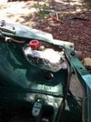
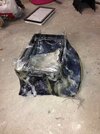
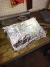
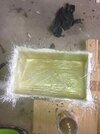
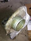
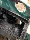
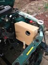
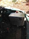
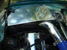
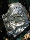
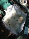
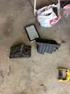
Started making a cold air intake box out of fibreglass. I had an air box from a N15 Pulsar and wanted to use it for a couple of reasons rather than running a pod filter.
1. With the box intake won't be sucking in hot air from the engine bay.
2. Pressurised box will improve air flow.

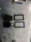
To improve flow I will be using a K&N element filter.

I know I'm probably opening a can of worms here but this is my opinion and the design I have decided to use.

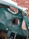
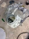
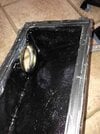
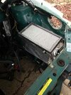
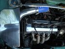
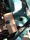
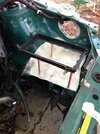
So the plan is to modify the N15 box, run ducting via enlarging the original intake ducting hole next to the coolant reservoir.

I will be relocating the battery so the filter will be sitting where the battery is, to feed the turbo.

Happy to hear opinions re: this air box vs a pod filter or if I can do anything to improve the design.

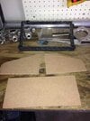
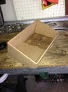
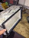
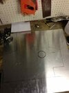
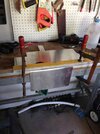
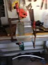
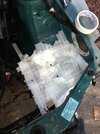
Started with a cardboard template.....
 

Attachments

  • 82137.jpg
    82137.jpg
    30 KB · Views: 55

CMF_Danvillan

» CMF Member
Member since:
Posts:
Then placed some foil over the tape so
1. The resin didn't soak through the masking tape and
2. It's easier to remove after fibreglassing

I placed the bolts in the holes so no resin blocked up the threads
 

Attachments

  • 82139.jpg
    82139.jpg
    40.7 KB · Views: 46

CMF_Danvillan

» CMF Member
Member since:
Posts:
The N15 OEM air box, which not very smooth inside as there if a lot of plastic ribbing for support which would reduce airflow a bit or at least cause some turbulence.
 

Attachments

  • 82141.jpg
    82141.jpg
    28 KB · Views: 41

CMF_Danvillan

» CMF Member
Member since:
Posts:
The only things I'm using from the N15 box is the 2 flanges to connect the 2 pieces of the box and the rubber mounts.

Also the exit of the box has a nice trumpet intake so I'll use that too

So cut the 2 flanges off and cleaned them up a bit with a die grinder and sandpaper, and removed the trumpet intake and thats all I need.
 

Attachments

  • 82142.jpg
    82142.jpg
    29.8 KB · Views: 38

CMF_Danvillan

» CMF Member
Member since:
Posts:
Next thing was to use something to support the bottom flange up off the fibreglass base.
I used some copper pipe which I hot glues into position, I'll remove these supports once the fibreglass is formed around the flange and base.
 

Attachments

  • 82143.jpg
    82143.jpg
    35 KB · Views: 40

CMF_Danvillan

» CMF Member
Member since:
Posts:
The next thing to do is wrap the whole thing with some material so the fibreglass can be placed over the top, sorry thought I got some photo of this step but forgot. I used a cotton shirt and some hot glue to do this process.

I then wrapped some foil around the coolant reservoir and fitted it into position, when I did this I used to washers to hold it out a bit as the reservoir will be used a part of the mould and once the washer are later removed there will be a small gap between the airbox and the reservoir.
 

Attachments

  • 82145.jpg
    82145.jpg
    35.4 KB · Views: 41

CMF_Danvillan

» CMF Member
Member since:
Posts:
So I didn't get any photos of the next couple of steps either but I put a couple of coats of fibreglass all over the box and put it into position the material conformed to the shape of the reservoir.

It was about this time when I realised that the airbox was going to be it the way of the headlight and I wouldn't be able to plug the wire into the back of the headlight... doh.

So had to jam a bit of whatever was lying around to make some space for the headlight. Luck I realised before the resin set.

Once set I removed the copper pipes and trimmed the the excess fibreglass.

The flange was a bit loose so I pop riveted the flange to the fiberglass and used some seal'n'flex to seal to underside of the flange to make it air tight

Two layers of Fibreglass placed inside the airbox.

Another couple of layer done on the outside and ended up looking like this....

Not too pretty at the moment but i'm going to cover it with insulated aluminium tape ( to reflect any engine bay heat) so you'll never see my bodgey fibreglass work, as long as its air tight.


Attachments

  • 82147.jpg
    82147.jpg
    31.3 KB · Views: 36

CMF_Danvillan

» CMF Member
Member since:
Posts:
To be continued...

To do.
1. Cut larger hole in the wheel well for induction pipe.
2. Cut matching hole in airbox and fibreglass a flange in airbox.
3. Do the top side of the box , which i have no idea of how I'm going to it at the moment.
4. Finishing touches,etc....
 

CMF_Danvillan

» CMF Member
Member since:
Posts:
Well continued with the airbox this morning.

Made a mould for the top part of the box by cutting some MDF to the profile I wanted the top of the box to be.

Hey DOOM hopefully it will turn out well, but not keen to make them to sell thats why I put the info on this thread so anyone can have a go at making one and learn from all the mistakes I make along the way.
 

Attachments

  • 82158.jpg
    82158.jpg
    26.5 KB · Views: 37

CMF_Danvillan

» CMF Member
Member since:
Posts:
While waiting for that to dry I cut a larger hole in the wheel well to increase the air flow to the box.

Once cut I placed the box in position and traced the hole to the box so I could see where I had to cut the air box
 

Attachments

  • 82162.jpg
    82162.jpg
    32.5 KB · Views: 39

CMF_Danvillan

» CMF Member
Member since:
Posts:
Cut the hole out of the air box and place the metal flange.

The flange is just a 100mm downpipe adaptor from bunnings I used this so I can later use some tek screw to connect the ducting from the front bar to this flange
 

Attachments

  • 82164.jpg
    82164.jpg
    36.5 KB · Views: 37

CMF_Danvillan

» CMF Member
Member since:
Posts:
I used a couple of pop rivets to secure the flange then fibreglass inside and outside of the flange.

I'm now waiting for the top half of the box to dry, be back later to show how its going.
 

Attachments

  • 82165.jpg
    82165.jpg
    29.2 KB · Views: 35

CMF_Danvillan

» CMF Member
Member since:
Posts:
sprayed inside of both halves of the air box with rubberised paint to help seal the box further. Also mounted the induction cone from the N15 airbox.
 

Attachments

  • 82170.jpg
    82170.jpg
    31.2 KB · Views: 38

CMF_Danvillan

» CMF Member
Member since:
Posts:
Cover both halves of the airbox with Aluminium flashing tape, it is a thin section of aluminium with a adhesive rubber backing. I thought that using this would deflect heat away from the air box.
 

Attachments

  • 82171.jpg
    82171.jpg
    29.9 KB · Views: 41

CMF_Danvillan

» CMF Member
Member since:
Posts:
with the top section on.

Damn the box is big but I suppose it will need to be when the T25 starts spooling up.

I think the design performance wise will work well but I'm not happy with how it looks aesthetically.

I'm thinking I will make up a Aluminium heat shield/cover to run down the side and over the top.
The aluminium can be polished to give a better look and also act as another heat shield. I might be happy with it then.
 

Attachments

  • 82174.jpg
    82174.jpg
    34.4 KB · Views: 36

CMF_Danvillan

» CMF Member
Member since:
Posts:
template transferred onto some aluminium sheet that I bough for $10 from the local fabricator.

Ready to be cut, folded and welded together.

Should look a bit better once covered
 

Attachments

  • 82210.jpg
    82210.jpg
    19.6 KB · Views: 35

CMF_Danvillan

» CMF Member
Member since:
Posts:
So cut the sheet up. Time to fold the bends, it was only light gauge 1.2mm or so.

Rigged up a couple of levels and clamps as a poor mans brake press. The corners are a little round but looks pretty good.

I did the top of the cover first as it was the biggest bend.
 

Attachments

  • 82330.jpg
    82330.jpg
    29.3 KB · Views: 30

CMF_Danvillan

» CMF Member
Member since:
Posts:
Test fit before welding. Looks a lot better with the cover especially once it's polished up.

Sent to my mates yesterday to be welded, it will be finished tomorrow.

Getting a couple of tabs welded to each side for mounting brackets.
 

Attachments

  • 82332.jpg
    82332.jpg
    30.4 KB · Views: 37

CMF_Danvillan

» CMF Member
Member since:
Posts:
Yeah it clears the bonnet. It's close at the front section near the radiator support probably only about 10-15mm clearance. There is quite a bit of head room under the Micra bonnet.
 
Back
Top