-
Please only use these forums for blogs, they are not a discussion forum
You are using an out of date browser. It may not display this or other websites correctly.
You should upgrade or use an alternative browser.
You should upgrade or use an alternative browser.
My long promised blog
- Thread starter h701micra
- Start date
OP
OP
h701micra
Deactivated Account
I shall do tomorrow for you ")
They're mounted in the top of the strut tower itself. Not how I wanted it buts that's how it ended up. But believe me there's room for em on there. Ive got a chunky 6n diesel setup under there and its no problem
You can weld a triangular plate from the top of the strut tower to the inner wing and drill into that (my original idea)
OP
OP
h701micra
Deactivated Account
So I took some pictures of that headgasket where it was blocked up baddd

You can see where I cleared some of them
Looks loke this engine wasnt as well maintained as I first thought
These are for Belly93

On my k10 there were small 3/4mm holes already in the top so I drilled them out and popped em in there. The large repair washers are a good recommendation too.
Mine also has a small steel tube on em with garden hose pipe round it to give the bonnet its lift for better airflow
A doddle on a k10 with how the bonnet opens

You can see where I cleared some of them

Looks loke this engine wasnt as well maintained as I first thought
These are for Belly93


On my k10 there were small 3/4mm holes already in the top so I drilled them out and popped em in there. The large repair washers are a good recommendation too.
Mine also has a small steel tube on em with garden hose pipe round it to give the bonnet its lift for better airflow
A doddle on a k10 with how the bonnet opens

fuhhh.... nice modification buddy.. respect..
Got another set of these today

CUSCO ?! or HWL ??
lucky for u guys over there still got those aftermarket adjustable abs...
here in my place, we need to specially customized our own to suit this model..
and it cost alot.. or another solution, we use to recondition to old one..
They're polo ones. Get em cheap enough simple to mod to a k10
just plug and play rite?!
good news for me...
yess.... thanks mate..
OP
OP
h701micra
Deactivated Account
They need fettling with to get em to fit. But they're easy enough on a k10just plug and play rite?!
good news for me...
yess.... thanks mate..


OP
OP
h701micra
Deactivated Account
I was just messaging you
Sure have
http://www.demon-tweeks.co.uk/motorsport/electronic-ignition-kits
Sure have
http://www.demon-tweeks.co.uk/motorsport/electronic-ignition-kits


OP
OP
h701micra
Deactivated Account
Thanks manNice work h701
OP
OP
h701micra
Deactivated Account
So I was fiddling with a set of coilovers just now and did this
Thought hmmm...
Needs a proper seat..
Mill and weld and voila! Low and stiff k10 stiff k10 suspension (I didn't mill and weld but I might with some different springs)
Non height adjustable but you can alter that by changing the spring free length and of course spring weights can be changed

Thought hmmm...

Needs a proper seat..

Mill and weld and voila! Low and stiff k10 stiff k10 suspension (I didn't mill and weld but I might with some different springs)

Non height adjustable but you can alter that by changing the spring free length and of course spring weights can be changed

Very nice
OP
OP
h701micra
Deactivated Account
Ok guys I need your help
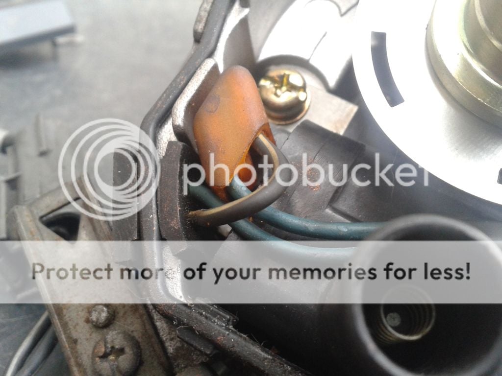
What does each pin do on the de dizzy? Cant find a wiring diagram
Here's the pins
An overview
The usual blue black coil wires
To coil
Sensor which replaces points
Will this sensor just need power. Thinking it needs management to decode data from it.
Need any and every idea going and some sort of wiring diagram
What does each pin do on the de dizzy? Cant find a wiring diagram
Here's the pins

An overview

The usual blue black coil wires

To coil
Sensor which replaces points

Will this sensor just need power. Thinking it needs management to decode data from it.
Need any and every idea going and some sort of wiring diagram
Enuo
Glorified Electrician
its a simple 2 condition sensor, on off. It detects magnetic flux which is absent when the slots come round. During the period the slots are under the sensor there should be a break in the signal to the solid state switch, that closes the circuit needed to discharge the coil through the dizzy. No high tech management needed. There should be an ignition module though I think.
Disclaimer: This is based off my installation of pertronix into a spitfire dizzy, and should not be take as gospel but rather a place to start.
Disclaimer: This is based off my installation of pertronix into a spitfire dizzy, and should not be take as gospel but rather a place to start.

Belly93
to turbo or new lump :/ hmmm
Like this
[/quote
whats this? looks good?
OP
OP
h701micra
Deactivated Account
Sure willwould it work on a k10?
OP
OP
h701micra
Deactivated Account
Wow I know very little about dizzysPoints replacement, just optical not magnetic like de dizzy is
Magnetic is totally new to me
OP
OP
h701micra
Deactivated Account
Similar threads
- Replies
- 137
- Views
- 2K
- Replies
- 11
- Views
- 3K